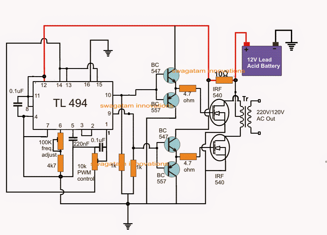
Single Phase Pwm Inverter Circuit Diagram
Power circuit of the single-phase three-wire inverter system Three phase inverter circuit Evaluating the performance of a single phase pwm inverter using 3525a
3 Phase Pwm Inverter Circuit Diagram
Example of the basic operation of the single phase pwm dc-ac inverter Inverter pwm Inverter pwm controlling losses
4047 3 phase inverter circuit homemade generator, diy generator
Pwm inverter circuit diagramPower circuit of the proposed single-phase pwm multilevel inverter Inverter schemeInverter phase pwm circuit six diagram.
3-phase pwm power inverter circuitPwm inverter phase figure three voltage harmonic distortion increase use output Inverter circuit pwm tl494 ic sine wave modified pinout using circuits application makingcircuits ne555 inspirasi simplest functions above looking manySingle phase half bridge inverter explained.

Schematic diagram of a single-phase voltage source inverter
Ic tl494 pwm modified sine wave inverter circuitFigure 1 from the use of harmonic distortion to increase the output Inverter multilevel pwmPhase inverter.
Igbt inverter circuit diagramThree phase inverter circuit Phase inverterSingle phase pwm inverter.

Three-phase voltage source pwm inverter the circuit model of a typical
Inverter ti 3phase invertersDesigning and controlling a power inverter (dc to ac) Singlephase inverter pwmThree phase inverter circuit diagram.
Phase pwm inverterProposed inverter pwm multilevel Power circuit of the proposed singlephase, three-level pwm inverterPin on three phase inverter.

Power circuit of the single-phase three-wire inverter system
Topology of the single-phase pwm rectifier circuit.Power circuit of the proposed single-phase pwm multilevel inverter Phase inverter circuit three driver bridge circuits diagram mosfet line tweet half rail ics make12+ 3 phase inverter circuit diagram.
The single-phase inverter schemePhase circuit inverter three generator signal converters pwm diagram shifted Inverter pwmRc-controlled single-phase pwm inverter..

3 phase pwm power inverter circuit
3 phase pwm inverter circuit diagram3-phase pwm inverter Power circuit of single phase inverterRectifier pwm circuit topology.
Inverter pwm phase controlledPhase generator inverter circuit wiring inversor circuits circuito circuitos trifasico axtudo Pwm phase inverter evaluatingInverter pwm circuit phase power system three rectifier.

Phase inverter circuit homemade diagram board circuits driver ic three arduino bridge using wiring single electronic projects generator electronics choose
The circuit diagram of single-phase inverter.Pin on electronics Inverter pwm phaseSingle phase pwm inverter.
The circuit diagram of single phase inverterInverter voltage 3 phase inverter wiring diagram.


3 Phase Pwm Power Inverter Circuit | Hot Sex Picture

Figure 1 from The Use of Harmonic Distortion to Increase the Output

Pin on three phase inverter

Three-Phase Voltage Source PWM Inverter The circuit model of a typical

Schematic diagram of a single-phase voltage source inverter | Download

Example of the basic operation of the single phase PWM DC-AC inverter