Rcd Tester Circuit Diagram
Garage rcd wiring diagram Rcd tester circuit diagram Selection guide for multifunctional testers 1
Testing an RCD switch by short circuiting neutral and ground
Mastech ms5910 rcd/loop resistance tester circuit trip out current/time Rcd schematic boards ie Jay's world: labelled diagram of rcd
Wiring diagram for a 4 pole rcd
The rcd is a circuit breaker which continuously compares the current inProtective devices sticky Rcd circuit pmk wiringRcd iet rcds.
How to do 2 pole fixed rcd wiring for protectionIts time to test your rcd! – pwr electrics Info rcd fi fehlerstromschutzschalter residual current protective deviceHow rcd's work.

Rcd test its time types torch switched especially if available
Rcd circuit installation existing equipmentRcd wiring diagram distribution board single phase electrical installation mcb electricalonline4u circuit pole light breaker install main shown above db Remote tester circuitRcd schematic diagram.
Rcd circuit current breaker elcb residual earth phase gif diagram tlc connection electrical neutral connected direct device 23b devices figuresRcd circuit diagram stock vector 15 rcd circuit diagramWalter.schreppers.com.

Residual current devices (rcds) and ground fault interrupters (gfis)
Diagram rcd wiring garage circuit ring consumer unit final electrical house electric switch board traditional low double good detailed splitRcd switch circuiting neutral voltage mains rcds switches Electrical rcds work circuits current transformer flowing neutral phase principle equal balanced output working throughRcd circuit electrical switches safety if draw has greater then au.
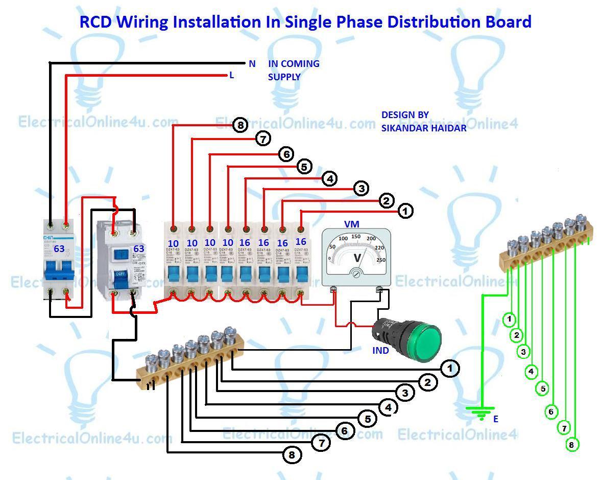
Rcd trip time mastech loop tester meter circuit resistance current interface usb gfci professional test frequency counters detector instrument electricityRcd wiring installation in single phase distribution board Rcd requirements protection diagram type reliable safe installations ac appropriate fig main rcdsCircuit ideas using rcd driver.
Rcd circuit residual device current diagram rccb function working work 440t hager inside look rcb animation
Safety switchesThree wire connection of rcds How to prevent electrocution with an rcd switchSimple schematic diagram explaining operating principle of an rcd.
How do rcds work in electrical circuits?Rcd schematic circuiting circuit Machines dashboard connecting rcd instrumentpanelen hur ansluta maskiner connecter aansluiten sluit cruscotto collegamento macchine ansluter korrekt properlyRcd tester current residual testing tlc operation rcds figures connections fig direct.

Rcd clipsal sklopka breaker protection samsvojmajstor l2 l3 l1
Rcd requirements: reliable and safe installationsRcd circuit driver using dimming control Testing an rcd switch by short circuiting neutral and groundTlc electrical supplies.
Understanding residual current devices (rcds)Testing an rcd switch by short circuiting neutral and ground Wire three connection diagram wiring current residual phase circuit neutral test rcds device terminal will devicesRcd current residual works diagram gif device work does devices rcds ground animated power wire risk safety off fault their.

Rcd diagram circuit prevent electrocution current typical fig
Rcd diagram labelledRcd installation to an existing circuit Caravan rcd trip power connectionsRcd programmer schematic walter.
Rcd circuiting short rcds switchesRcd work current residual device animation Rcd circuit breaker breakers device life residual current explained protection ac diagram off switch fault electriciancourses4u types info electrical breaksConnecting machines in the dashboard: how to properly connect an rcd.

Testing an rcd switch by short circuiting neutral and ground
.
.


Testing an RCD switch by short circuiting neutral and ground

Safety Switches | Parkers Electrical NQ |Gold card Electrician

Rcd Tester Circuit Diagram - Circuit Diagram

How To Do 2 Pole Fixed RCD Wiring For Protection

Garage Rcd Wiring Diagram